 Your new post is loading...

|
Scooped by
Gust MEES
|
|
|
Scooped by
Gust MEES
|
1.Vorwort zur Arduino Anleitung
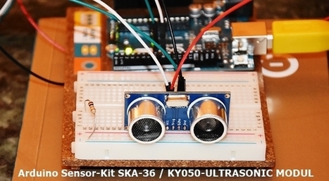
Diese Anleitung soll als Grundlage zum Erlernen der Arduino-Plattform dienen. Sie soll Anfängern einen einfachen, interessanten und eng geleiteten Einstieg in die Arduino-Thematik geben. Die Anleitung orientiert sich dabei hauptsächlich an praxisorientierten Aufgaben mit einer theoretischen Einführung vorab. Diese sollte man vorher unbedingt lesen, um bei den späteren Praxisaufgaben nicht an Kleinigkeiten zu scheitern.
Diese Anleitung ist im Rahmen einer Unterrichtstätigkeit entstanden. Sie kann kostenlos zum Erlernen der Arduino-Plattform verwendet, jedoch nicht ohne Erlaubnis kopiert oder anderweitig verwendet werden. Die Anleitung wurde sorgfältig erstellt und wird kontinuierlich gepflegt, jedoch wird keine Garantie für die Richtigkeit und Vollständigkeit übernommen.
Für die praktischen Aufgaben sollte man mit einigen elektronischen Bauteilen versorgt sein. Auf dieser Internetseite können sie passende Arduino-Sets bestellen, die speziell auf diese Anleitung zugeschnitten sind.
Learn more / En savoir plus / Mehr erfahren: https://www.scoop.it/t/21st-century-learning-and-teaching/?&tag=ARDUINO
|
|
Scooped by
Gust MEES
|
|
|
Scooped by
Gust MEES
|
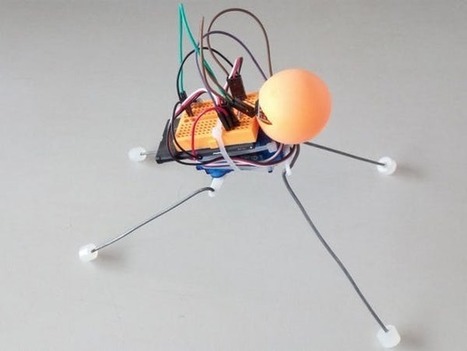
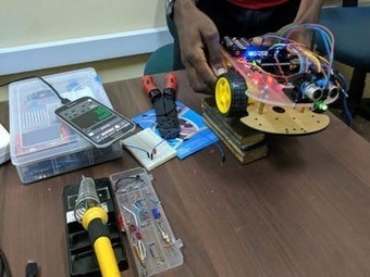
Here is a quick and easy little robot that can be built and assembled in about half an hour with the right tools and parts.
I didn't invent it. I saw a video of a thing like this on YouTube and thought 'Hey, that looks fun, I'll build one.'
So I grabbed some servos out of my junk box, an old cellphone battery I had kept in the hope of finding something cool to do with it, an arduino pro 3.3v that I had bought on a whim because I needed to reach the quota for free delivery and went to work.
An hour or so later, here it was!
Let's start with the basic assembly.
Cut off the mounting arm that's opposite the side where the wires come out on one of the servos (This will be your back servo). The back servo points down and the other forward. You can use glu or cable ties to keep them together. Learn more / En savoir plus / Mehr erfahren: https://www.scoop.it/t/21st-century-learning-and-teaching/?&tag=ARDUINO
|
|
Scooped by
Gust MEES
|
|
|
Scooped by
Gust MEES
|
|
|
Scooped by
Gust MEES
|
|
|
Scooped by
Gust MEES
|
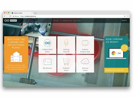
Today, at Embedded Linux Conference 2018, Arduino announced the expansion of the number of architectures supported by its Arduino Create platform for the development of IoT applications. With this new release, Arduino Create users can manage and program a wide range of popular Linux® single-board computers like the AAEON® UP² board, Raspberry Pi® and BeagleBone® as if they were regular Arduino boards. Multiple Arduino programs can run simultaneously on a Linux-based board and interact and communicate with each other, leveraging the capabilities provided by the new Arduino Connector. Moreover, IoT devices can be managed and updated remotely, independently from where they are located.
To further simplify the user journey, Arduino has also developed a novel out-of-the-box experience for Raspberry Pi and BeagleBone boards, in addition to Intel® SBCs, which enables anyone to set up a new device from scratch via the cloud without any previous knowledge by following an intuitive web-based wizard. Arduino plans to continue enriching and expanding the set of features of Arduino Create in the coming months. Learn more / En savoir plus / Mehr erfahren: https://www.scoop.it/t/21st-century-learning-and-teaching/?&tag=ARDUINO
|
|
Scooped by
Gust MEES
|
|
|
Scooped by
Gust MEES
|
Mechatronics is a multidisciplinary field of science that includes a combination of mechanical engineering, electronics, computer engineering, telecommunications engineering, systems engineering and control engineering. As technology advances, the subfields of engineering multiply and adapt. Mechatronics' aim is a design process that unifies these subfields.
A mechatronics engineer unites the principles of mechanics, electronics, and computing to generate a simpler, more economical and reliable system. The term "mechatronics" was coined by Tetsuro Mori, the senior engineer of the Japanese company Yaskawa in 1969. An industrial robot is a prime example of a mechatronics system; it includes aspects of electronics, mechanics, and computing to do its day-to-day jobs.
Engineering cybernetics deals with the question of control engineering of mechatronic systems. It is used to control or regulate such a system (see control theory). Through collaboration, the mechatronic modules perform the production goals and inherit flexible and agile manufacturing properties in the production scheme. Modern production equipment consists of mechatronic modules that are integrated according to a control architecture. The most known architectures involve hierarchy, polyarchy, heterarchy, and hybrid. The methods for achieving a technical effect are described by control algorithms, which might or might not utilize formal methods in their design. Hybrid systems important to mechatronics include production systems, synergy drives, planetary exploration rovers, automotive subsystems such as anti-lock braking systems and spin-assist, and everyday equipment such as autofocus cameras, video, hard disks, and CD players. Learn more / En savoir plus / Mehr erfahren: https://www.scoop.it/t/21st-century-innovative-technologies-and-developments/?&tag=Mechatronics https://www.scoop.it/t/21st-century-learning-and-teaching/?&tag=Mechatronics
|
|
Scooped by
Gust MEES
|
|
|
Scooped by
Gust MEES
|
|
|
Scooped by
Gust MEES
|
|
|
|
Scooped by
Gust MEES
|
|
|
Scooped by
Gust MEES
|
|
|
Scooped by
Gust MEES
|
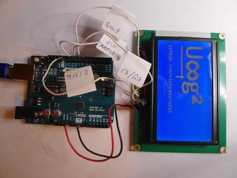
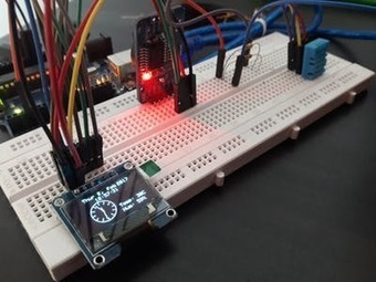
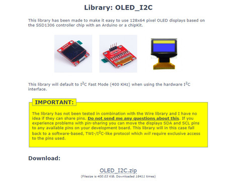
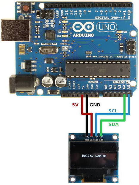
How to connect and program the Geekcreit 0.96 inch 4 pin white I2C OLED module with Arduino. OLED display based on a SSD1306 OLED driver IC.
In this tutorial a 0.96 inch monochrome OLED display from Geekcreit is connected or interfaced to an Arduino. Libraries are then installed and some example programs run which show how to use the display in an Arduino sketch.
The display connects to Arduino using only four wires – two for power and two for data, making the wiring very simple. The data connection is I2C (I²C, IIC or Inter-Integrated Circuit). This interface is sometimes called TWI (Two Wire Interface).
At the very lowest level, the Arduino Wire library is used to communicate with the display. Libraries are available that make it easy to start using the display right away to display text and graphics. These libraries are installed in this tutorial. [Gust MEES] It works with THIS OLED <===> https://www.amazon.de/dp/B01L9GC470 Learn more / En savoir plus / Mehr erfahren: https://www.scoop.it/t/21st-century-learning-and-teaching/?&tag=ARDUINO
|
|
Scooped by
Gust MEES
|
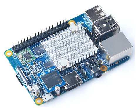
FriendlyElec has released a $35 rival to the Raspberry Pi 3 B+, outdoing the better-known board with 2GB of memory, Gigabit Ethernet, and a more powerful GPU.
The NanoPi K1 Plus follows FriendlyElec's Nano Pi K2, released last year with similar dimensions to the Raspberry Pi 3 for $40.
The NanoPi K1 Plus shares similar specs to the Nano Pi K2 and maintains the Raspberry Pi's form factor, but offers double the RAM, Gigabit Ethernet, and 4K video playback.
The device also has the same 40-pin GPIO pin-header as the Raspberry Pi 3, so it should work with Raspberry Pi accessories and housings.
Instead of the NanoPi K2's 1.5GHz Amlogic processor, FriendlyElec opted for an Allwinner H5 quad-core 64-bit Cortex A53 processor that runs at 1.4 GHz as well as a six-core Mali450 GPU. The Raspberry Pi 3 B+ uses a 1.4GHz Broadcom BCM2837B0, Cortex-A53 ArmV8 64-bit SoC.
The NanoPi K1 features three USB 2.0 ports, one microUSB 2.0 port for power, a microSD slot, while wireless support includes 802.11 b/g/n. Learn more / En savoir plus / Mehr erfahren: https://www.scoop.it/t/21st-century-learning-and-teaching/?&tag=Raspberry+Pi
|
|
Scooped by
Gust MEES
|
|
|
Scooped by
Gust MEES
|
|
|
Scooped by
Gust MEES
|
|
|
Scooped by
Gust MEES
|
|
|
Scooped by
Gust MEES
|
|
|
Scooped by
Gust MEES
|
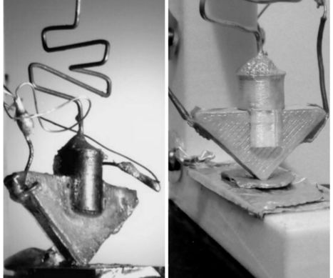
Didactic model of the "first transistor".In this project the models such as constructing a didactic model of the first transistor for which I made use of the materials that can be easily obtained, in addition to a little painting, the prototype / model I did on a scale a little larger than the original. But from before, a bit of history.It all started at Bell Labs, where American physicists Jhon Bardeen, Walter Houser Brattain, and William Shockley conducted experiments and observations to try to create a solid-state amplifier, making use of the properties of semiconductor materials, thus replacing the Vacuum used at that time.The above image shows the first transistor created at Bell Labs in Murray Hill, New Jersey, United States in 1947. Its inventors won the Nobel Prize in Physics in 1956 for "their research on semiconductors, and the discovery of the transistor effect." Now we continue with the instructions... Learn more / En savoir plus / Mehr erfahren: https://en.wikipedia.org/wiki/Transistor http://www.scoop.it/t/21st-century-learning-and-teaching/?&tag=makered
|
|
Scooped by
Gust MEES
|
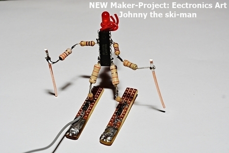
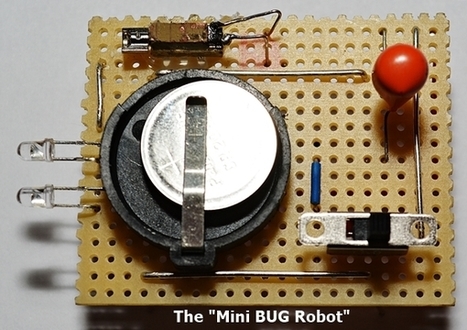
The Mini BUG Robot In last blog post (tutorial) WE were practicing OUR soldering by creating "JOHNNY the ski-man", a bit "Electronics-Art" using electronics components. In the video below, which I created with the FREEWARE <===> Windows Movie Maker <===> WE see ALSO "The Mini BUG Robot" who gives "JOHNNY" a ride. It… Learn more / En savoir plus / Mehr erfahren: http://www.scoop.it/t/21st-century-learning-and-teaching/?tag=electronics
|
|
Scooped by
Gust MEES
|
|


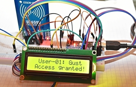


RFID RC522 Tag-Card Reader with LCD1602-I2C - We were already playing around with LCD's in our previous tutorial <===> First Steps with the Arduino-UNO R3 | Maker, MakerED, Coding | Super Starter Kit UNO R3 Project | LCD and Sensors Project <===> but there we used the SPI-Bus, meaning: connecting 12 wires (Potentiometer connections included...)!! With the I2C Bus we need ONLY to connect 4 wires!!
Learn more / En savoir plus / Mehr erfahren:
https://www.scoop.it/t/21st-century-learning-and-teaching/?&tag=ARDUINO
https://www.scoop.it/t/21st-century-learning-and-teaching/?&tag=I2C
https://www.scoop.it/t/21st-century-learning-and-teaching/?&tag=LCD
http://blog.mklec.com/how-to-use-iici2c-serial-interface-module-for-1602-lcd-display/